
Friday, March 25, 2016
Writing a tool that works for you..
Sometimes you just gotta write a little piece of software that prompts you for an image (of a waveform), and in seconds turns it into raw data you can paste in your microcontroller code.

Saturday, July 25, 2015
Updates..
Haven't updated this in quite a while. Bout time!
In the last couple years, I went ahead and built a couple batches of both the Hollow Earth tremolo and Anti-nautilus granular audio destroyer. Not as much as I had hoped, but that's a couple dozen more out in the world, and that's better than none at all!


Unfortunately, in unfun ways, sometimes life gets in the way of being productive, so I had to put batches aside for a while while focusing on real job/other things.
Lately though, I've been building new designs again (first since 2012)! Dabbling in the modular synth world (a sequencer pictured below) and two new pedals.
The one I'm most excited about, a 14-second delay/looper, pictured below. Also, there is a video:


Less interesting is this 3-in-1 dirt, here pictured:


So what does the future hold? Summing the energy to build a couple more batches of the anti-nautilus for one. Then looking ahead to building a few of that delay above (who still needs kinks ironed out). Also, a refresh of the hollow earth. Something simpler, maybe with a few less features, but with far less menu-diving.
Currently on the bench, experimenting with codec chips, meaning high-ish fi audio processing potentially. And more DSP. A simple looper, and bitrman killer.
Sunday, October 14, 2012


Wednesday, August 8, 2012
Anti-nautilus (or, autoglitch)
Anti-nautilus theory

Giant interdimensional nautilus portal right into the cities of the world! Most people, those who will not run, will grab baseball bats, mace, bad art, even a sword! What do I do? Fight it with lasers of course! Lasers are the nautilus' natural enemy, as often observed in the natural world. Not having xeon gas at my disposal, I turned to the tools I knew well and built a stompbox laser.
The Anti-nautilus focuses a beam of.... err.. sorry.... it continuously samples audio input, and once a (settable) input threashold is hit, unmutes and plays back the previous snippen of sound back-and-forth in a kind of glitchy lasery freeze effect. The duraction of the audio sampling during lasering is set by the Buffer knob, and the Break knob provides additional stuttery-ness to it! It can sort of be seen as a very short looper too, ranging between 1000-th of a second to 1 second. Additional control over Pitch bending (up or down) while the duration of the lasering can be set. It can be locked to single octaves, or as much as the design can handle, in this case 6 octaves. A Fade knob provides decay over time in much the same way. External trimpots are there for the input gain, output effect volume, wet/dry blend and "trigger thresh" sensitivity.
Short version: It's basically an auto-glitch, auto-repeat thing with tweakability.
One green LED to show whether the effect is bypassed or not, and a purple LED to indicate when input threshold is achieved.
Picking out the hardware
I was already familiar with 8-bit AVRs (programmed using BASIC), but extra horsepower was really needed here. So I forced myself to learn C and the new PIC32 hardware. Mikroelectronica's little MINI-32 is a great way to get started! It's breadboard-friendly, and has a USB plug for easy programming. I wasn't going to use it for the final layout, but it's great for prototyping. For what I had in mind, the PIC32's internal 16KB of RAM was enough, so no need for external memory.
I needed an ADC and a DAC for audio. DAC was an easy choice. I had a bunch of PT8211's at hand which I was already familiar with! It's cheap (half a dollar each), easily found, easy to interface, small 8-pin package, 16-bit, fast and sounds good! I had my DAC.
ADC was gonna be trickier. I had spent much of the year researching and getting samples of 16-bit ADCs for whatever applications. 16-bit ADCs in a small easy to use package are a dying breed, everybody wants to use codec ICs now, which are a little overwhelming for me at the moment. I found a couple, but they were expensive ($12-$16), and were noisy. I settled instead for the MCP3201. It's 12-bit and quite a bit slower, but it worked for my needs. And it's far far quieter in terms of unwanted noise. Because of the slower speed, I had to limit the program's sampling rate to 22KHz, even if the PIC32 and much faster DAC could easily handle 100KHz (by my tests).
The PCB layout and schematic were drawn out in DipTrace.


What went right
Designing a solid programmable hardware base with 12-bit input and 16-bit output! I have a feeling I'll make a few developpement PCBs with this setup so I can easily and quickly start a new digital project! I'd probably want to fix the 12-bit ADC into 16-bit, though, and I'll want to tack on some external RAM. I think with a few modifications, I can make a nice little DSP dev board!


What went wrong
Using unsigned data format for audio storage instead of signed. Hooooo boy.... ok. How I went through the entire developpement was by storing audio input in an 8000-strong unsigned word array. Each "word" is a single sample, a value based on amplitude at that given moment that produces a number anywhere between 0 and 65535. That's 16-bit data. I'm not saying that's the best way, just how I did it.

That looks fine, doesn't it? It plays fine, anyway. Now below I've drawn out what took me over a week to figure out, without the aid of visuals or the experience of having dealt with hi-fi ish audio. I had most of the program done and working well, and I implemented the fade feature. I wanted to fade the audio by X amount every time the "loop" looped (or reversed direction). Except when I implemented that feature, I'd get an audible click or pop at each fade point. I thought I was goofing up the fade formula, or that I was "forgetting" to fade every first or last sample of the loop, or something. My UART was broken (thing I can plug into computer and see debug numbers sent by microcontroller), and my cheap oscilloscope was too limited to show me the "big picture" of what was happening. it literally took a week and a half of trying new code, listening for changes, guessing, rewriting the code on how the loop reverses direction, etc. Thinking the pop was a single sample that went up to 65535 because of a glitch, or something. Was data improperly being sent to the DAC? Or from the ADC? Had to test that too. No dice. Then one day I did what I should have done on day one, and simple recorded the pops with my soundcard and looked at the waveform.

....uhhh... wh.... oh... OOOOHHHHHHHH! Oops!
Those yellow lines in the otherwise beautiful sine wave represent what I was more-or-less seeing (though not so colorful). The click/pop was NOT some odd dropped sample, it wasn't some glitch when I told my loop to reverse direction, it was that I wasn't using the right data format. I understood it the second I had the visual clue in front of me. I was using unsigned (0-65535) data format, so whenever I told my program to "fade", it would shrink the waveform towards the arbituary 0 floor, and not towards the "center" of the waveform. Oops.
Once I recognized the problem, I tried hacking a solution by tricking my fade code that the number 32767 was the center of the universe, but that gave me more problems elsewhere in the program. I even tried non-destructive crossfade at each-loop point if I was fading. Not super easy to do when the loop is actually a reversal in playback direction. Didn't work. I accepted I had to change the fundamentals of the audio data format, that it couldn't simply be scotch-taped in. Blergh.
Unsigned data is 0 to 65535. Signed data is -32767 to 32767, where the "center of the universe" is exactly 0. This makes much more sense in the audio world. I converted parts of my code into signed format. My PCB was already done, so whatever changes had to be in code. Once the conversion was (mostly) done, I noticed that absolute silence wasn't exactly 0, likely because of the 5% tolerances of whatever resistors I was using in front of the ADC. I coded in an extra +200 "data" to each sample to offset it to 0. Close enough.

Much better. It's actually exagerated in this picture. The filtering I had in the circuit post-DAC took care of the rest. I will be using signed data for audio in these types of projects from now on.
Art
I had a pretty good idea of what kind of art I wanted on the pedal half-way through developpement. A giant squid, octopus or other tentacled entity wreaking havoc on humanity. Isn't that the best way to go? The sound of the pedal was "laser-ish" from conception, but I didn't want to do UFOs or particle accelerators. Definitely lasers though! Either attacked by or defending with. It took actual experimentation with a breadboarded prototype. I found I could get some really organic and "crawly" sounds out of it, as well as lasers! The idea of a giant many-limbed invertebrate settled into place shortly after. Oh, I know! A nautilus! I haven't drawn any of those yet!
The picture was clear in my mind, and what I like to do for images of that complexity is model it in 3D first. My day-job involves working quite a lot with 3DS Max, a professional 3D package. It's far more intuitive for me to sculpt objects in virtual 3D space than to sketch things in 2D and have to erase and start parts over. I didn't need details yet, just basic shapes. After a couple hours, I had this:

Then a few hours in photoshop to trace outlines and add details. I couldn't fit any lasers in the pic, so I was treading onto plot-hole territory. But I fugred the sounds I got from the thing were crawly and spacy enough to portray the grander terrifying invasion. This will be applied on a transparent decal.

Painting is fairly straightforward. A base layer of acrylic primer is applied and left to set for a day. A few base layers of acrylic paint is brushed on by hand. I usually dilute it with water. Say one part water and two parts paint. I have a small heating fan that I like to "bake" paint layers with. It's small, but next to a pedal, can easily raise it to toaster-oven temps! Also, it makes more sense to me to pick bring colors as the base layer, then go over it with dark later, instead of trying to paint bright on dark.
After base layers, combining toothebrush-spray-on splatter and hand-painted spirals and shapes to give it fun! I try and keep the areas which will have decals bright, so that the transparency works and is contrasted. I keep "baking" the box with the floor fan in-between steps and when I'm finished, sucking most of the water out.
I use Lazertran for laser printers. Fitting for the nature of the pedal! On it I print the picture I vortexed out of the 11th existencial plane, the border trim, and the words that will be under knobs and toggle switches. The printed decal is soaked in water, then seperated from the opaque backing. I apply it to the dried paint like a temp tattoo, with a bit of water based clear in-between! I have a few minutes to push the bubbles out or guiding them to the nearest pot hole. Let it sit for a while, then I do the heating fan trick again, though at a much lower heat! This kind of "melts" the decal (which is essentially plastic) deep into the paint. The lower heat is to keep it from bubbling, though a little isn't a problem.
One of the most important steps, clear coat! I've taken a liking to clear epoxy resin, rather than traditional spray or brunched-on clear coats. The disadvantage is that it's rather expensive (a $30 bottle will last you around 10 pedals), messy (don't drip it, it can't be washed. ever.) and hard to find in precisely the right viscosity. It's applied in one single thick syrupy coat with a plastic spoon! Why viscosity is important is that if it's too thin, too liquidy, it'll run off the sides of the box too much and won't provide adequate protection there. The thicket it is (when "wet"), the more of it will stick to the sides. The top isn't a problem, it hardens to a mirror shine without any polishing! Normally, it takes about two days to harden, but after letting it set for one, I can do the heating fan trick again, bringing it down to just a fistful.

Thursday, March 29, 2012
Been busy!
In a couple senses of the term. Not too many updates last year because of a lot of personal stuff. But I have been busy! Especially in the last couple months!
The Hollow Earth
The new version I mean. It's already been posted about (scroll down). I still don't have a video about it, and it's still not ready for release. There's been *one* problem that's keeping it from being accessible. It's a power issue. In some cases, on some amps/guitar/power combinations, it's extremely noisy. I think it's some sort of ground loop or "virtual ground" problem. It's fine and perfect in many situations, but unusable in others. I'm not very knowledgable when it comes to the physics bhind electronics, grounding issues and whatnot, and this seems to be exactly the problem. The physics of it. Thats why it's taking so long (again). I've gone through about 4 revised PCB prototypes so far, still no dice.
On my own amps, on my own guitars and own power supplies, in the electricity in my home, I have no problems whatsoever. It's been so hard figuring this out. What a headache this design has been!
Vibrato

This is a refresh of that vibrato I made! General improvements, including a wet/dry blend for pseudo-chorus, and a blendable crackle/noise/scratch sim (like vinyl). I'm building 10 of these. Unsure whether I should leave the noise blend in or not.
Here's a video:
http://www.youtube.com/watch?v=r7az_xhgJcQ
I'm kind of terribad at pedal video demos. The second half is better. That's because I let an ebow do all the work.
Compound


I think just watching the prototype video will say everything:
http://www.youtube.com/watch?v=2oMQ8IRSZkU
Saturday, October 8, 2011
FB
Sonic Crayon FX now has a FB page. Should make updates and info easier..
http://www.facebook.com/pages/Sonic-Crayon-FX/230721366984881
http://www.facebook.com/pages/Sonic-Crayon-FX/230721366984881
Friday, June 3, 2011
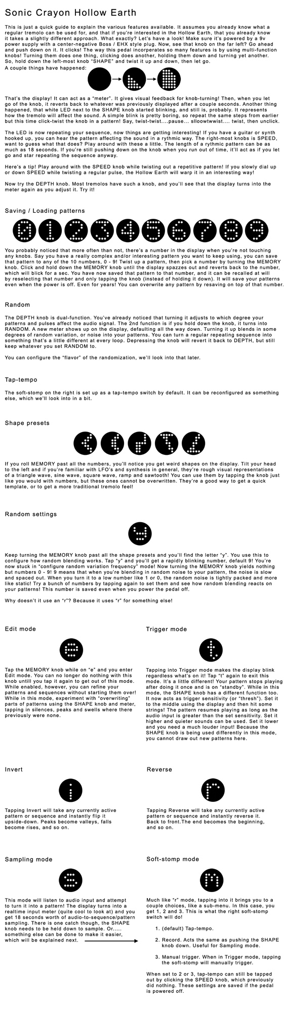
HE v2 "sampling" mode brainstorm
Is a glitchy "sampling" mode on the new HE better than no "sampling" mode at all? The intent is to have a mode that records sound input and turns it into an envilope. Here's how I'm doing it so far:
20 sub-samples are taken from the input at 5ms intervals, then averaged. the average becomes the main "sample" that lasts 100ms. this occurs 10 times a second.
so it samples at a total of 200hz. the problem is when I hit a note like low E (82-ish hz), or any note really, that the played note will get pretty close in-phase with my sampling frequency from time to time as it "drifts". because of that, for an entire 100-200 milliseconds, it'll only be sampling the "dips" in-between the sound waves and will average close to 0, even though to our ears the note rings loud and clear. as clear as it was when it was sampling at the peaks of the same waves 300ms earlier! the result is a stuttery glitchy envelope instead of smooth envelope following.
adding circuitry is a last resort (there's barely any room left on the PCB). so far I've tried:
1. adding offsets of 2.5ms every 2 samples to try and average an equal number of wave dips and peaks.
2. only keeping the very highest sample out of 20
3. ignoring sudden drops of envelope if the next one goes right back up again (loss of detail)
Increasing the sampling frequency is difficult at the moment since the whole foundation of the bare-bones design is built around 20 sub-samples per "real" sample, because of the interpolation I'm doing. I think I'll try adding a timer interrupt that samples much more/faster and independantly of the rest of the program.
Thursday, May 26, 2011
Hollow Earth prototype
v2.0 prototype. It works really well! Things left to do on firmware is the sample-from-sound-and-turn-into-LFO mode, a dedicated random mode, and some tweaks to the simple random blend you can add to existing LFOs.


Thursday, April 28, 2011
Mockup

1:21 AM blog post! Just a graphic mockup of what I think the new hollow earth will probably look like.
Oh yeah, just got back from seeing Godspeed You! Black Emperor, that was pretty fantastic!
/random
Sunday, April 24, 2011
Hollow Earth redesign proto
Found the time to (mostly) finish the new prototype this weekend. What's left to be done is ironing out the few glitches and adding a couple modes in software. Specifically:
-menu to assign a function to the soft-stomp.
between tap tempo, shape record and manually triggered envelope
-a mode where it samples and makes an lfo/envelope based on
input sound. could be pretty rad for drum machine stuff!
-I should probably make an option to invert whatever shape
...oh yeah, and definitely what's my densest/most insane PCB layout. It'll take a few weeks to arrive, though.

Sunday, March 27, 2011
1165 lines of code..
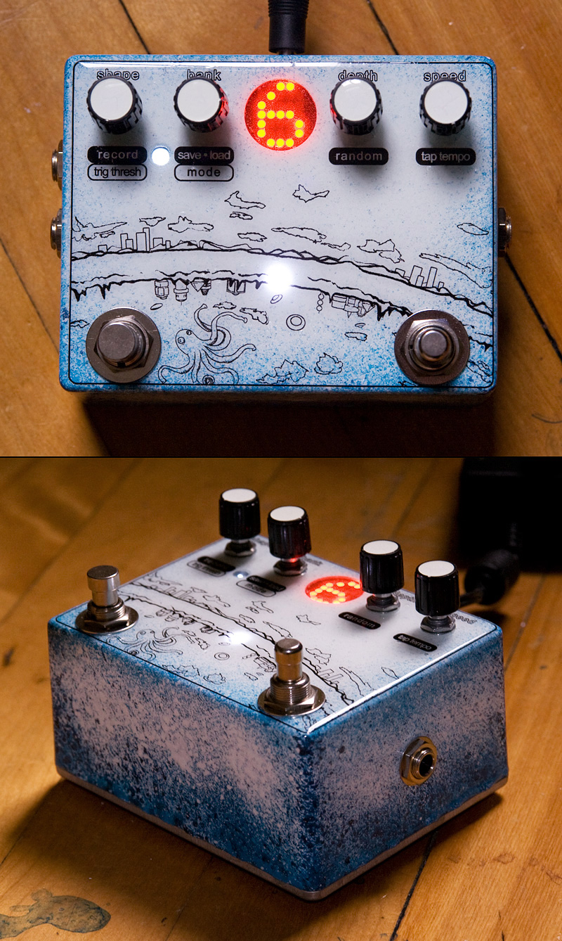
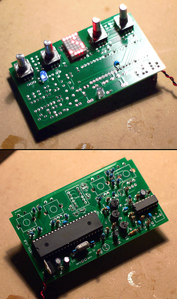
..though a bunch of it was copy pasted. I figure I'm about 95% done the new hollow earth, at least programming-wise. Hardware-wise, an AVR dev board, a few rotary encoders, a trimpot, an led and a 5x7 led matrix is all I've been staring at these past few weeks.

Four knobs is probably all you'll need! They're all multi-function. Turn for one thing, hold down and turn for another, tap for another, etc.
A bit of tech info. I'm using an atmega644 uC. It's got 64KB program memory but so far I'm using only 17% of it. I needed the 2KB of eeprom it offered for preset storage. When recording custom LFO shapes, it samples at 10 a second for up to 18 seconds. And then it's interpolated times 20 to smooth it out. Speed is full adjustable while recording and after, obviously. 10sps is plenty for slow human hands, but I'll offer the user to fine tune this in a sort of "preferences" mode.
Let's see, checklist. What's done, and to-do..
(software)
-expressive display
-hook up PWM output (with freq doubling)
-do custom LFO record/playback
-x20 interpolation!
-speed control
-tap-tempo
-depth control
-random blend
-preset saving/loading
-square/triangle/ramp/sine/saw hard preset LFOs
-shape edit
-trigger mode
-multimode tap footswitch
-preferences/options
(hardware)
-LDR biasing
-power filtering
-clean tl074 buffer
-CV out
-polarity protection

Four knobs is probably all you'll need! They're all multi-function. Turn for one thing, hold down and turn for another, tap for another, etc.
A bit of tech info. I'm using an atmega644 uC. It's got 64KB program memory but so far I'm using only 17% of it. I needed the 2KB of eeprom it offered for preset storage. When recording custom LFO shapes, it samples at 10 a second for up to 18 seconds. And then it's interpolated times 20 to smooth it out. Speed is full adjustable while recording and after, obviously. 10sps is plenty for slow human hands, but I'll offer the user to fine tune this in a sort of "preferences" mode.
Let's see, checklist. What's done, and to-do..
(software)
-hook up PWM output (with freq doubling)
-do custom LFO record/playback
-x20 interpolation!
-speed control
-tap-tempo
-depth control
-random blend
-preset saving/loading
-square/triangle/ramp/sine/saw hard preset LFOs
-shape edit
-trigger mode
-multimode tap footswitch
-preferences/options
(hardware)
-LDR biasing
-power filtering
-clean tl074 buffer
-CV out
-polarity protection
Saturday, March 19, 2011
led matrix visual feedback
clicky encoders are annoying. ordered some non-clicky ones.
with the push-for-secondary-function knobs and the display now offering an expressive level of visual feedback, I've been able to simplify the next hollow earth pedal to just 4 push-knobs and one toggle at the back of the enclosure!
this was a huge priority because it means I can PCB mount everything on a single board this time!
Sunday, March 13, 2011
LED matrix app
So I got myself a couple tiny 5x7 LED matrix displays to tinker around with. I thought they might be a nice replacement to 7-segment displays. On the new Hollow Earth, I'm using a microcontroller with a greater number of pins, so I think it's doable. Might make for some neat animation, too!
Then my mind caved in at the thought of manually typing binary data for each PIXEL. It's pretty daunting to do by hand, because each LED in the matrix does NOT have its own pin. Instead it's a row and column array where you have to carefully "render" the LEDs, line by line, applying positive power to cathodes where you *don't* want pixels, and so on. Arrrrghhhhhhhhhhhhhhhhhh..........
Too much, I said, so what do I do? I install something I haven't used in like ten years, Visual Basic 4.0.
An hour later, I have made an app where I can draw a number, letter or graphic just by clicking on squares, and then automagically spits out code and/or raw binary data I can simply paste in my micro!
Whatta time saver!

Writing a program that writes code for you. How zen!
Wednesday, March 2, 2011
Redesigning a fundamentally awkward design..
so yeah..
I've started a complete Hollow Earth redesign. I really want to see it being sold again and the old design was just so difficult. Being on two PCBs, socketed ribbon cables, wired switches, hacks and tricks giving each build it's own little quirks. I've had enough of all that. The old one was designed when I was just beginning to understand microcontrollers almost two years ago and I've learned a lot since. Time to do it right, this time.
Instead:
-single PCB design
-everything PCB mounted, except jacks
-rotary encoders instead of pots, with double functions
(turn does one thing, push and turn does another, or just push, like tapping the speed knob for tap tempo)
-less parts (no "shape" stompswitch for one)
-in-program interpolation, no more smooth knob
-and so on
Probably no more vactrols either. They were a pain to bias properly so that CV-out and the actual tremolo effect played nicely together. Gonna try digital potentiometers instead.
UPDATE: I'm afraid trigger mode will probably go the way of the dodo. It never worked THAT great, and it's one of the major roadblocks in my simplifying.
Tuesday, December 21, 2010
OT: New music website thingie..
I've finished a new website for my various musical projects (not really DIY-related). So now instead of pointing people to a myspace, I can just send them to this:
www.dronecloud.org
www.dronecloud.org
Sunday, December 12, 2010
Crushed Glass granular sampler/looper/glitcher

This is something I've been working on (on-and-off) since january or febuary of '10. For DIYers, looping is usually restricted to ISD sound recorder chips. They are neat but don't offer a whole lot of flexibility. I wanted totally random access to individual samples for some pseudo-granular drones so I saw what I could do with microcontrollers. Initially I had started learning dsPICs, but later put it aside and went with what I knew, the 8bit AVR.
I'm using SPI RAM which isn't the fastest solution but I just wanted to see if my ideas could be done. Fidelity was secondary. I went with the ATMEGA328 which is the chip with the most amount of internal RAM in DIP format. I didn't want to use the larger 40-pin DIPs.
I wanted to be able to ping-pong the "playback head" in as little time as a 1ms sample window, define start and end loop points, among other things. That meant quite a bit more code that simple record and playback. Keeping it tight, I still manage up to 12KHz sampling on the 8-bit uC. Considering there's a lot of SPI communication with both RAM chips and the DAC, I don't think that's too bad. Stuff like LED updates and potentiometer sampling only happen around 20 times a second. I use an additional uC (atmega88) on a daughter board for the 16 LEDs. It serves as a 4-to-16 decoder.


On the less technical side, sound-wise it is pretty lofi. It doesn't handle complex recordings well. Stuff like full chords, mixed-down songs, things with a lot of harmonic detail and smooth volume dynamics. Some complex things work, most don't. What it does handle well is individual monophonic instruments (or picking single strings on a guitar), some vocals, cicuit bend noises, and it handles electronic beats really well!
The controls are really counter-intuitive, and for this reason I won't be building these for anybody just yet. There are some bugs and limitations that I have not been able to fix in the weeks and months of work. The problem is that I designed this back-to-front which is a really bad way of doing things. I started building a looper then later tacked on features. It's all duck-taped and bandaided together with tricks and hacks in the code. What I should of done is figure out my features first, then design around that. Because I did the reverse, fixing the bugs and limitations have been so difficult that I'll have to start over if I intend to sell these. Personally I can live with these quirks, but I can't help but think others would be confused.
The next one will be much better!

A list of features/controls, some more technical information and a video below.
- Input gain (with red clipping LED)
- Independent Dry and Wet knobs
- Record / Playback toggle switch (with purple rec LED)
- Hard bypass toggle switch (with orange LED)
- Low pass filter
- 16 LED "head" position
- Speed, sets the samplerate
- Start and End realtime sample trimming
- Trim drift/gradual offset
- Confusion knob which does ping pong stuff to the "head"
- Direction knob sets forward or reverse, or glitchy in-between madness!
Main CPU: ATMEGA328 (overclocked to 12mhz at 3.3v)
Secondary CPU: ATMEGA88 (for 16 LEDs only)
ADC: internal 8bit
DAC: external 12bit MCP4921
RAM: two 23k256 ICs
LPF: MAX7403
Programmed in BASCOM
Thanks for reading/watching!
Saturday, June 12, 2010
3 bitcrushers for sale *SOLD*
as of now.
$150 US
tracked and insured shipping is around $15 to north america. contact me if elsewhere.
Check the blog post down below. Some samples are there. has samplerate reduction, bitcrushing on an 8-position knob, wet/dry blend and volume. good for lo-fi effects, nintendo/atari sounds, weird digital fuzz, glitches, etc. great on synths and drum machines too! does a good job killing fidelity! when turning up the volume and harshness, with the wet/dry knob all the way "dry", it's not totally dry. more like 96% dry. uses 9v DC standard boss-like adapter. not included. Meant as a non-subtle effect but subtle can sort of be dialed in. Full refund if you dont like it (assuming it's in okay condition, and minus shipping). will try and ship before monday.
*SOLD*
Thursday, June 10, 2010
Moth bitcrusher sale
I'll have three bitcrushers for sale in a few days.

two samples. both tentatively co-titled the-art-of-dicking-around. I have no idea what I'm doing. I've never been good at recording dirt-only stuff, at least without some kind of backing.
http://nearworlds.org/stuff/diy/moth1.mp3
http://nearworlds.org/stuff/diy/moth2.mp3
they'll officially go on sale sometime on saturday for $150 US each, but only as of when I update this blog on that day saying so. so please no emails ahead of time. when the time comes, you can reach me at:
eblythe (aaaat) mochamail (dooooot) com
Friday, May 21, 2010

Thursday, April 29, 2010
Sonic Crayon Moth + Hollow Earth plans
hookay....
Things have been lagging due mostly to demotivation re: the hollow earth. That sucker is tough to build, I mean really tough. it's definatelly not dead, though, and as a way to help kick-start things back up again, I'm selling off a batch of bitcrushers/samplerate reducers with wet/dry blend control. it's an easy build I'll have no trouble building a dozen of, and at the same time it'll help refinance the whole hollow earth gig.
So here's the bitcrusher, called the Moth and does 1-8 bit crushing and samplerate reduction. there's wet/dry blending and volume as well. the graphic will change a little. here's a bad clip. I'll do a youtube once things are orginized.
there will be no reservation list for this one. in a bunch of weeks I'll just announce a day they go on sale and that'll be that. $150 a pop.

in semi related news, the kind folk at Audio Effekte have written a kind word on this project of mine, as well as about montreal assembly!
read it here
You should check out Scott's stuff (at mtl assembly). he makes rad effects too and his bitcrushers are way more versatile than mine! face-melting boxes galore!
Saturday, April 3, 2010
Meanwhile..
..I'm thinking of doing a small run (10) of simple samplerate reduction pedals to try and kick things back up again. Two knobs (blend and samplerate), simple circuit, etc. 10x easier than the hollow earth and would help fund/re-enthusiate an eventual hollow earth reincarnation.
Maybe.
Maybe.
Tuesday, March 23, 2010
Hollow Earth non-update
I'm super late with Hollow Earth orders, in case you were wondering.
big surprise
big surprise
Sunday, February 14, 2010
of floopers and bitcrushers
A quick flooper (feedback looper) I built for the Pines. Saw it in action at a show last night, awesome!

Also, an old video of that bitcrusher I forgot ever existed:

Also, an old video of that bitcrusher I forgot ever existed:
Sunday, January 31, 2010
DIY Synth log #2

Little board I made to help me in developping the programmable synth. Seeing how so many things need to be controlled by DACs (for preset recall and automation), made a little 16-channel multiplexer with sample-and-hold.
Still shopping around for a simple 16-bit DAC. most are either SMD, or are I2S (too slow) instead of SPI. And I can't spare the pins for parallel. Eugh...
Sunday, January 10, 2010
DIY Synth log #1
Some sounds I had lying around:
http://nearworlds.org/stuff/diy/diy_synth_01.mp3
http://nearworlds.org/stuff/diy/diy_synth_02.mp3
Part of a long-term project of building a synth. The rough outline is:
-3 or 4 oscillators. sine, square, triangle, ramp
-2 or 3 LFOs for FM, AM and VCF
-1 noise generator
-lots of LFO shapes, including "manual" waveshaping
-resonant VCF (using SSM2044)
-2 ADSRs for amplitude and VCF
-programmable delay (based on 2399)
-savable patches
-real wood enclosure and 2-octave keybed!
-some kind of basic arpeggio/sequencer
-MIDI-in a big maybe. I haven't looked at MIDI yet
I'm using DSI-type synths (evolver, prophet) as inflluence for the design. Digital control of analog stuff! In the sounds above, I'm using a atmega88 microcontroller to drive an MCP4921 DAC which in turn drives an analog XR2206 function generator. The 12-bit resolution of the DAC gives me a range between 30hz to around 8khz with tolerable drift. The micro has a table of all DAC values for 92 notes. The samples are straight from the oscillator. There's no envelope, filter, LFO or anything. The delay in the first one was added in soundforge for kicks. The "sequencing" is hard-coded in the micro.
The XR2206 is basically a voltage-controlled oscillator with sine/triangle/square outputs, and ramp with a bit of tweaking. It's really simple to use and requires almost no external components!
I'm gonna need a lot of DACs. One for each oscillator, for each LFO/ADSR combo. I intend to do the LFOs and ADSRs in code to make them flexible and as low-part-count as possible! I think I can mix both LFO and ADSR in code and have it use just one DAC.
I'm hoping to make the delay as dynamic as possible! Time and decay modulated by keys and LFOs and whatnot! If I can fit all components for a single "voice" (a dozen chips, I'm guessing) i nsmall-enough space, then I might consider making this a 4-voice synth. The main micro would just have to keep track of which voices are available, and if none are, use the one that was pressed the longest time ago.
I don't know yet if I want to salvage a wooden enclosure from something or just make my own. I haven't done any sort of woodworking since when I was a kid. It's not hard, but I am sort of ill-equipped! I'm not worried for the keybed. Doepfer has some nice OEM ones.
Saturday, December 26, 2009
Next batch..
Having major issues with the new batch of PCBs. Can't figure out what it is. If I ever do find out what it is, and if it's serious, then the next batch will be delayed another two months, and a lot of wasted money.
I wish I could drop everything.
I wish I could drop everything.
Thursday, December 24, 2009
Hollow Earth orders
Hi,
I am no longer taking orders for the Hollow Earth. I need to get through the current list. This thing has been too much of a time eater, cost and source of stress, and I need to figure out what to do.
I am no longer taking orders for the Hollow Earth. I need to get through the current list. This thing has been too much of a time eater, cost and source of stress, and I need to figure out what to do.
Tuesday, December 15, 2009
new HE PCBs are in

4'th revision Hollow Earth PCBs are finally in (7 week wait, ughhh), so I'll get started on builds #12-18 shortly.
fixes include using surface-mount switches instead, some additional noise filtering (not that it was much of a problem before), volume adjustments, and stuff that'll make building them easier for me.
Monday, November 30, 2009
vibrato

vibrato I built for someone. design similar to the one I made months ago (down the blog) with some improvments/bugfixes.
and yes, still making Hollow Earths. it's just taking time to get through thel ist is all. and yes as of 2010 they will be $275 instead of $200. I underestimated the cost in time and materials when I initially started making them. sorry about that. people on the list have already been informed.
Wednesday, November 25, 2009

Subscribe to:
Posts (Atom)